Table of Content
Transitioning a newly arrived copper granulator from a wooden delivery crate to a productive, high-purity metal recovery plant requires structured foundation preparation, precise electrical sizing, and disciplined operational commissioning. Successful commissioning requires casting a reinforced concrete pad of at least 150 mm thickness, providing clear electrical working space under OSHA 1910.303, calibrating air table vibration and blower damper angles, and executing a structured 40-hour first-week maintenance schedule. I examine the civil foundation engineering, electrical drop sizing, pneumatic calibration steps, and daily operator training protocols below to ensure seamless plant startup.
What Foundation and Physical Space Requirements Must Be Prepared?
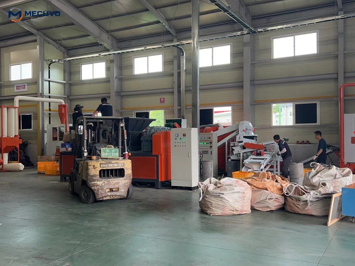
Before your granulator arrives on site, civil engineering preparation ensures the equipment operates without destructive structural vibration or cramped access. Cast a reinforced concrete slab of at least 150 mm to 200 mm thickness using C25/30 grade concrete, ensure level tolerances within 2 mm per meter, and maintain minimum 1.2-meter service aisles around all sides. To minimize unplanned downtime, scrap yards should maintain a dedicated inventory of recommended spare parts for copper wire granulators, including replacement screen decks and knife sets.
Civil Engineering, Concrete Specifications, and Floor Anchoring
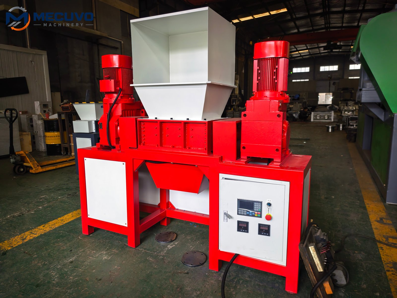
Industrial copper wire granulators combine high-speed rotating cutting shafts (400 to 600 RPM) with low-frequency eccentric vibrating air tables (300 to 500 RPM). Operating such equipment on cracked, uneven, or thin unreinforced concrete floors results in dynamic resonance that loosens frame fasteners, misaligns cutting knives, and transmits severe vibration to adjacent office structures or neighboring equipment.
For compact units such as the MECUVO CG-100 (approximate weight 1,800 kg) or mid-sized systems like the CG-200 (approximate weight 2,000 kg), cast a monolithic reinforced concrete slab of minimum 150 mm thickness reinforced with steel mesh. For industrial systems such as the CG-500 (3,500 kg) or CG-1000 lines (5,800 kg), increase slab thickness to 200 mm to 250 mm. Use heavy-duty M16 or M20 wedge anchor bolts or chemical capsule studs to securely anchor the machine base to the slab pursuant to OSHA 29 CFR 1910.212(b).
Working clearances must comply with statutory workplace safety mandates. Under OSHA 1910.303(g)(1), maintain a minimum clear working space depth of 3.0 to 4.0 feet (0.9 m to 1.2 m) in front of electrical control cabinets, and ensure access aisles remain completely free of stored scrap bales or forklift traffic.
How Should Electrical Drops Be Sized and the Air Separation Table Calibrated?
Proper electrical power delivery and delicate pneumatic airflow calibration govern whether your granulator operates smoothly or suffers chronic nuisance tripping. Size supply conductors in accordance with IEC 60204-1 / NEC Article 430 (feeder conductor ampacity rated for at least 125% of the largest motor full-load current plus the sum of all other continuous motor loads), coordinate branch circuit protection with motor starting inrush characteristics, verify voltage drop under 3%, and calibrate air table damper velocity until copper granules travel steadily uphill without boiling.

Electrical Inrush Protection and Pneumatic Bed Tuning
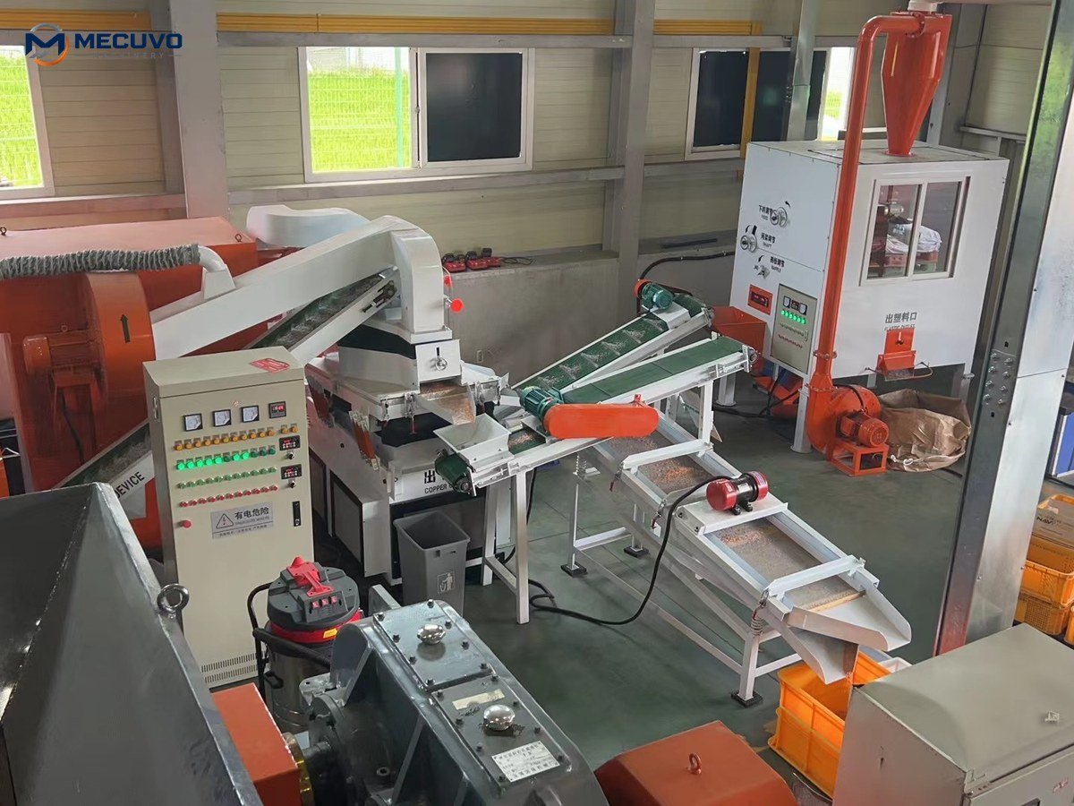
Electrical sizing must account for simultaneous motor starts. A mid-sized granulation line incorporates multiple three-phase induction motors: the primary granulator rotor motor, air blower fan, eccentric table vibration motor, discharge conveyors, and dust collector pulse-jet compressor. Under IEC 60204-1 and NEC Article 430, supply conductors must be sized to carry at least 125% of the largest motor’s full-load amperage plus the sum of all other simultaneously operating motors, with feeder voltage drop restricted to under 3% under continuous peak load. Branch circuit overcurrent protective devices (breakers or motor circuit protectors) must be selected by a qualified engineer to accommodate high-inertia rotor starting currents (via VFD ramp-up, star-delta, or soft starters) while ensuring coordinated thermal trip protection. Ensure dedicated working clearance around electrical control cabinets (typically 3 to 4 feet depending on system voltage and grounded building elements) to maintain safe maintenance access and permit unobstructed 90-degree door swing.
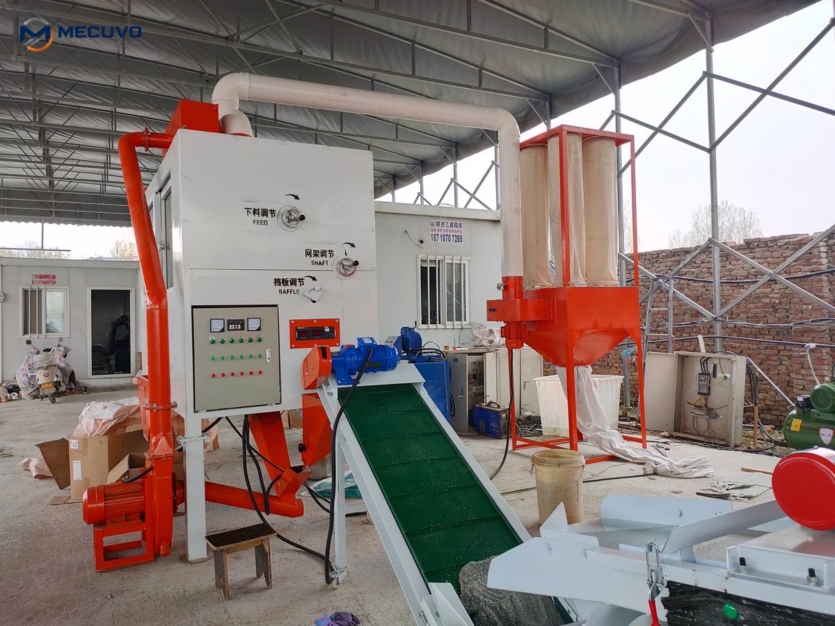
Once electrical power is verified and rotational direction confirmed, the most critical commissioning task is calibrating the vibrating air table:
- Deck Inclination Adjustment: Adjust the longitudinal deck slope (typically 4° to 7° upward toward the copper discharge). A steeper angle slows copper progression, increasing residence time and purity; a shallower angle accelerates throughput.
- Airflow Damper Setting: Slowly open the blower throttle valve while feeding wire chops. The bed of material should gently fluidise—resembling a dense liquid. If the airflow is too high (‘boiling’), copper granules will be blown over the plastic weir; if airflow is too low, plastic flakes will pack into the copper bed.
- Vibration Frequency: Adjust the eccentric drive speed via the variable frequency drive (VFD) so that heavy copper particles travel steadily uphill while light plastic floats downhill toward the tailings chute.
| Calibration Parameter | Optimal Operational Indicator | Problem Indicator (Under-Set) | Problem Indicator (Over-Set) |
|---|---|---|---|
| Airflow Volume (CFM) | Fluidised gentle bed, clear separation boundary | Plastic packs into copper discharge | Copper blown backward into plastic tailings |
| Deck Longitudinal Slope (Incline to Copper Discharge) | Uniform 25–40 mm copper band traveling steadily to upper discharge | Rapid dirty discharge, unseparated middlings carrying over (incline too flat) | Sluggish copper uphill progression, material stalls and overloads deck (incline too steep) |
| Eccentric Vibration Speed | Smooth forward progression without bouncing | Stagnant material bed, screen blinding | Chaotic bouncing, fluidised bed collapse |
| Knife-to-Bed Gap | Clean shearing cuts without wire folding | Blade collision / rubbing risk under thermal expansion (gap set too tight) | Pinched, smeared, and torn wire strands (gap set too wide) |
What Should Your Team Follow in the First-Week (40-Hour) Commissioning Checklist?
The first 40 operating hours of a new machine represent the critical infant-mortality window where mechanical settling and fastener relaxation occur. Execute mandatory re-torquing of all cutting blade bolts at 8, 24, and 40 operating hours, log bearing temperatures hourly, inspect screen mesh for blinding, and train operators in daily cleaning SOPs.
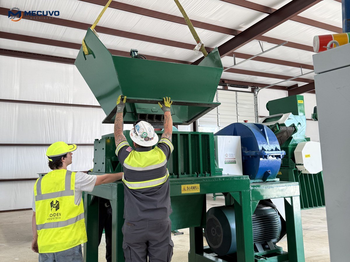
The 40-Hour Critical Commissioning Schedule
New granulators undergo significant mechanical bedding-in during their initial operating shift. Fasteners clamping the tool-steel knives to the rotor and bed seats experience thermal cycling and cyclical cutting impacts that cause initial micro-settlement. Under ISO maintenance standards, your team must adhere to a strict first-week checklist:
- Shift 1 (Hour 8): Shut down and lock out main power. Open the cutting chamber hood. Using a calibrated torque wrench, check and re-torque every rotor blade bolt and bed knife bolt to factory torque specifications. Verify that the 0.25–0.35 mm knife gap remains uniform across the rotor width.
- Shift 2 (Hour 24): Repeat knife bolt torque checks. Inspect main drive V-belts; newly fitted belts experience initial elongation and require re-tensioning to prevent slipping. Check grease purge on main rotor pillow block bearings.
- Shift 3 (Hour 40): Inspect the vibrating air table woven wire mesh deck for loose clamping strips or pinhole punctures. Inspect the pulse-jet dust collector hopper to verify that reverse-pulse cleaning cycles are dislodging fine dust into the collection bin.
Operator training must instill disciplined daily cleaning routines. At the end of every operating shift, operators must purge the cutting chamber by running the machine empty for 2 minutes, vacuum fine dust from the air table plenum chamber, and visually verify that no tramp steel or wire coils are wrapped around the rotor shaft. Scrap yards operating without heavy grid infrastructure can explore single-phase, three-phase, or generator power for granulators to size wiring and rotary converters safely.
For factory commissioning support, wiring schematics, and recommended starter maintenance kits, contact our technical services team via the MECUVO contact portal.
Key Takeaways
Rigorous installation on a reinforced concrete slab, precise air-table fluidisation tuning, and disciplined 40-hour bolt re-torquing ensure your copper granulator achieves maximum metal purity and long-term operating reliability.
— YOUR RECYCLING PROJECT
Find the right machine for your material.
Tell us your material and required capacity.
Or email sales@mecuvo.com