Table of Content
Fine conductors in telecommunication cables, Cat5e/Cat6 network wire and electronics ribbon cable can be carried into plastic or other residual streams during granulation. Recovering them requires machine-specific cutting and separation settings verified in representative trials. Use only OEM-approved screen sizes, knife clearances, airflow and vibration settings; assess secondary recovery from measured copper losses rather than assuming a universal setup or yield. Fragment size and shape, feed composition and machine settings all affect separation.
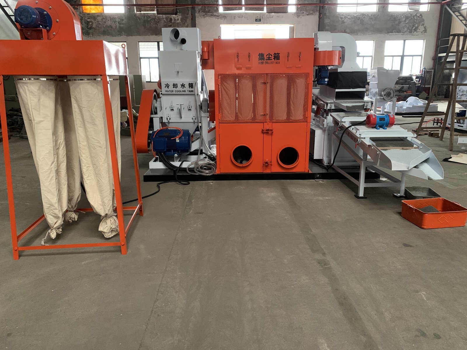
Why does hair-thin wire behave differently inside an aerodynamic separator?
Fine-wire fragments may have a high surface area relative to their mass, making them susceptible to carry-over with the light fraction. Coarser wire may produce more compact fragments, but particle shape and separation behavior depend on the actual feed and cutting conditions rather than wire gauge alone.
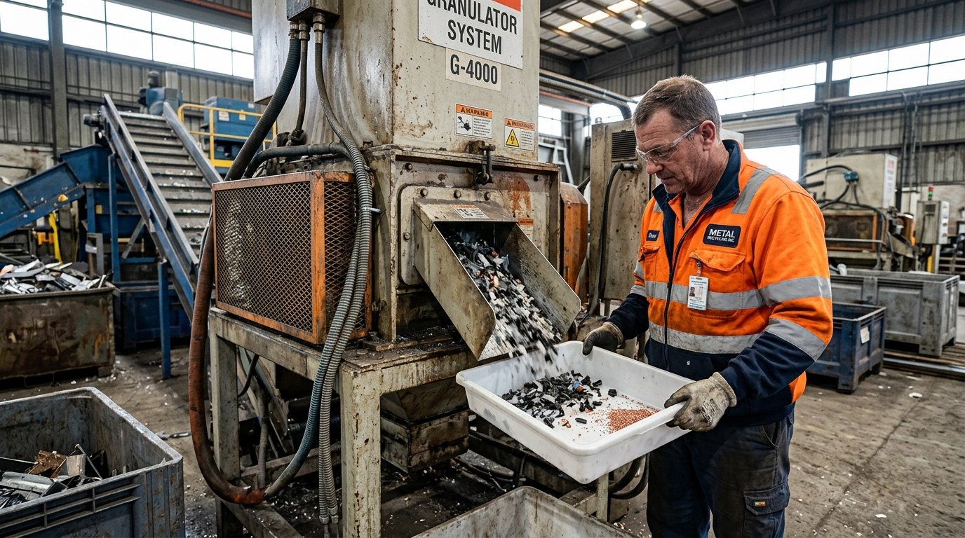
Particle shape, aerodynamic drag, and fine-wire carry-over
The fundamental challenge of processing Category 5 (Cat5), Category 6 (Cat6), USB, HDMI, and telecommunication switchboard wire is aerodynamic particle geometry:
- Compact Fragments and Curled Fine Wire: Cutting can produce particles with different lengths, shapes and surface areas. Fine strands may bend or curl rather than forming compact granules; inspect representative output instead of assuming a fixed aspect ratio, instantaneous settling or a single particle shape for a given cable gauge.
- Terminal Settling Velocity ($V_t$): In fluid dynamics, the terminal settling velocity of a particle in an upward airstream is determined by its mass, frontal projected area, and aerodynamic drag coefficient ($C_d$). Curled fine-wire fragments may have high aerodynamic drag relative to their mass. Their behavior depends on particle geometry and separator conditions; the quoted universal terminal-velocity intervals are not a validated operating basis.
- Aerodynamic Carry-Over: Fine copper fragments can enter the light fraction depending on size, shape, feed rate and separator settings. Measure copper in each output stream during representative trials rather than assuming a universal airflow or 4%–8% loss rate.
How do you mechanically calibrate the cutting chamber for fine data cables?
Use the manufacturer’s specified knife clearance, blade geometry and approved screen options for the exact machine and feed. Before accessing knives or changing screens, trained personnel must isolate and lock out all hazardous energy, control stored energy and verify isolation under the applicable lockout/tagout procedure. Refit guards before restarting. Verify wrapping, throughput and separation behavior in representative trials.
Blade gap tolerances, aperture bridging, and screen blinding prevention
Liberating microscopic insulation from ultra-fine copper strands requires precision mechanical shearing tolerances:
- Knife Gap: Inspect knife condition and set clearances only to the model-specific service specification after energy isolation. Do not substitute a generic 0.15 mm gap.
- Screen Aperture: Compare OEM-approved screens in controlled trials, measuring throughput, fines and separation performance. Smaller holes do not by themselves guarantee a particular output length or recovery.
- Investigating Screen Blinding: Cable fillers, fibers, moisture, particle shape and static effects can contribute to screen blockage. Inspect the actual material and follow the OEM’s cleaning and troubleshooting procedure. Any grounding, ionization or other equipment modification requires a suitably qualified assessment and manufacturer approval; it is not a universal cure for bridging.
What airflow and vibration settings stabilize the air density table for fine wire?
Fine-wire separation requires controlled trials within the manufacturer’s permitted airflow, vibration and deck-angle range. Record feed conditions and copper in each output stream; no single velocity, VFD frequency or mesh count is a universal recipe.
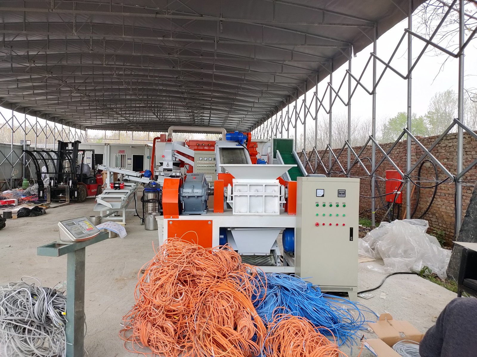
Superficial fluidization velocity, deck mesh count, and eccentric stroke tuning
After cutting, assess air-table performance on representative fine-wire feed within the manufacturer’s approved operating limits:
- Fluidization Airflow: Adjust only within the approved operating range and measure actual separation performance. VFD frequency does not uniquely establish air velocity through every deck.
- Deck Vibration: Use the approved speed, stroke and loading limits; increasing frequency beyond the design limit is not a valid general tuning instruction.
- Deck Cloth: Select the manufacturer-approved weave, wire diameter and aperture. Mesh count alone does not determine aperture: 40 mesh is not universally 0.38 mm.
When should a secondary electrostatic separator be evaluated for fine-wire recovery?
Electrostatic separation may recover conductive particles from some mixed residual streams, but suitability depends on the separator design, particle size, liberation, moisture and other feed conditions. Use representative tests to measure additional copper recovery, product purity, capacity and operating costs. Neither 99.2% tailings recovery nor 99.8% total-line recovery should be assumed without documented results for the specified material and configuration.
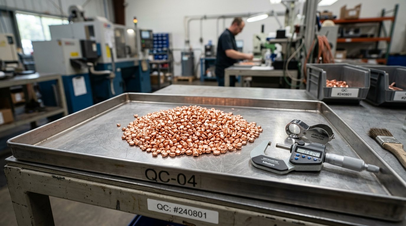
Electrostatic separation principles and measured recovery economics
There is no universal wire-diameter threshold that makes secondary electrostatic separation mandatory. First measure copper losses in each residual stream. If those losses justify further recovery, ask the supplier to test the actual or suitably representative tailings and confirm the equipment requirements and test scope in writing:
- Feed and Equipment Requirements: In a corona-roll separator, particles encounter a high-voltage field near a grounded roll. Confirm the permitted feed size, moisture, composition and operating conditions with the equipment manufacturer. High-voltage settings and safeguards are model-specific and must be handled under the approved operating and maintenance procedures.
- Different Electrical Responses: Conductive and insulating particles can respond differently to charging and contact with the grounded roll, allowing collection into separate streams. Actual separation depends on material and machine conditions; a universal discharge time or perfectly clean output cannot be inferred from conductivity alone.
- Recovery and Purity Verification: Electrical separation does not guarantee capture of every fine particle. Weigh and sample the feed and all products and residual streams during an agreed test, calculating copper recovery separately from product purity. Confirm any minimum particle-size or performance claim with test records for the quoted machine and feed.
- Incremental Financial Return: Estimate additional saleable copper from measured tailings mass, copper content and secondary-stage recovery. Apply the buyer’s actual price and deductions, then subtract added energy, labor, maintenance and other costs. Trial results and a stated feed tonnage do not establish a guaranteed monthly profit.
Review the MECUVO copper granulator machines overview, or contact MECUVO about fine-wire processing options. Request model-specific specifications, representative test records and written confirmation of any offered equipment, trials and charges.
Key Takeaways
Granulating fine data cables requires validated, model-specific cutting and separation settings. Quantify copper recovery and product purity separately in representative trials; a secondary electrostatic separator does not by itself guarantee a particular total recovery.
— YOUR RECYCLING PROJECT
Find the right machine for your material.
Tell us your material and required capacity.
Or email sales@mecuvo.com