INDUSTRIAL SIZE REDUCTION AND PRE-SHREDDING

Dual Shaft Shredder for Tough, Bulky and Mixed Materials

Reduce bulky waste and difficult industrial materials into manageable pieces with a low-speed, high-torque system configured around your actual feed.

  • Configuration matched to material and operating conditions
  • Multiple cutter, chamber and drive options
  • Automatic reverse and overload protection
  • Standalone machine or complete recycling line
  • Material testing before final configuration

Send material, maximum size, required capacity and expected output.
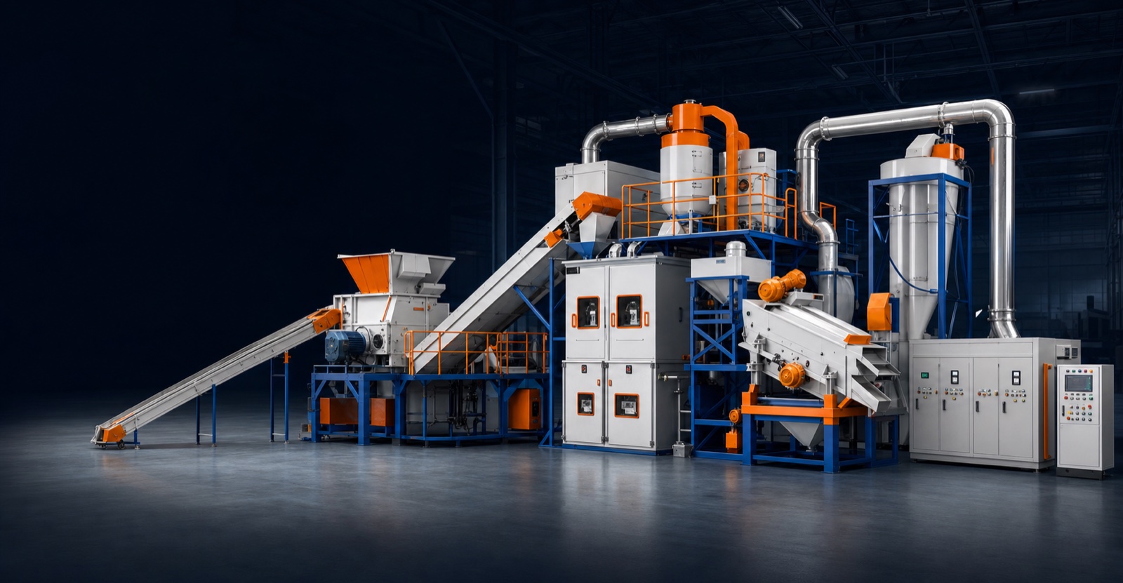
REAL SHREDDING TEST

Industrial recycling line placeholder for dual shaft shredder
Built in China
Configured for Your Application
Supported for Export

START WITH THE MATERIAL

Start With the Material, Not Just Motor Power

A larger motor does not automatically mean a better shredder. Composition, dimensions, density, contamination, feeding and downstream process determine the system.

01

What Are You Shredding?

Material type, composition and contaminants.

02

Maximum Feed Size

Length, width, diameter, thickness and weight.

03

Required Capacity

Hourly throughput and daily operating hours.

04

Expected Output

Reduction, opening, destruction or final-size target.

APPLICATION FIT

Your Shredder Must Do More Than Turn the Shafts

The machine must grip material, resist impact, manage overloads and produce output suited to the next process.
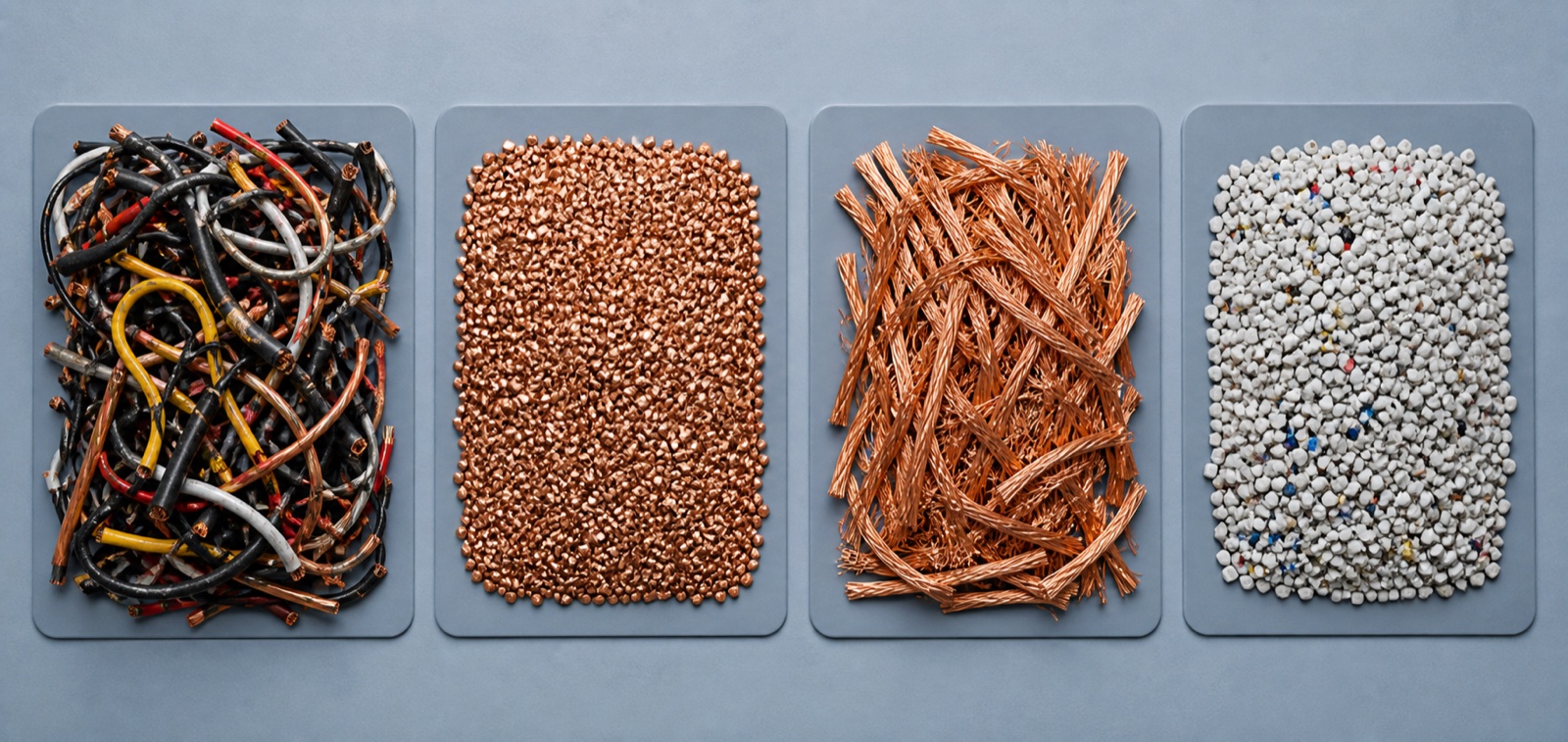
COMMON PROBLEMS

Incorrectly Selected Shredder

  • Material rotates above cutters
  • Shafts stop under thick or irregular loads
  • Output is too large downstream
  • Cutters wear faster than expected
  • Flexible material wraps around shafts
  • Maintenance access is impractical

REQUIRED RESULT

Correct Shredding System

  • Reliable material intake and stable torque
  • Automatic overload response
  • Matched cutter and shaft configuration
  • Practical maintenance and spare-parts plan
  • Conveyor and downstream compatibility
  • Documented configuration before production
Material input and output placeholder

COUNTER-ROTATING CUTTER SHAFTS

HOW IT WORKS

How a Dual Shaft Shredder Works

Two intermeshing cutter shafts rotate inward, grip the feed and tear, shear and compress it at low speed with high available torque.

  • Feed by hand, loader, grab, crane or conveyor
  • Hooks pull material into the chamber
  • Cutters shear and tear the feed
  • Controls stop and reverse on overload
  • Coarse material discharges for the next process

The cutting system—not the exterior—determines performance.

01

Material Feeding

Manual, loader, grab, crane or conveyor feed.

02

Material Gripping

Cutter hooks pull material toward the chamber center.

03

Shearing & Tearing

Counter-rotating cutters reduce the feed.

04

Overload Response

Controls stop and reverse the shafts when required.

05

Material Discharge

Coarse output leaves for collection or further processing.

APPLICATIONS

What Materials Can a Dual Shaft Shredder Process?

The same cutter and drive configuration should not be used for every material. Final suitability requires material review or testing.
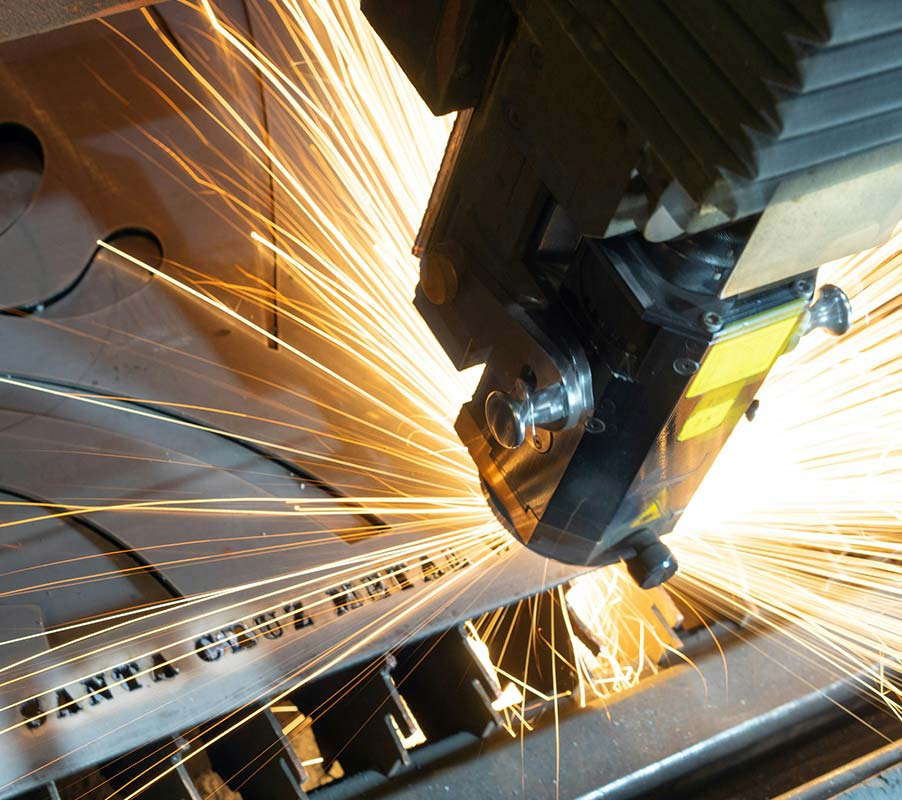
Industrial cutter and machining placeholder

Light & Medium Metal Scrap

Sheet, drums, profiles, frames and thin-walled production scrap.

Configuration depends on dimensions, composition and target output.

Material input and output placeholder

Plastic Drums & Containers

HDPE drums, crates, pallets, housings, lumps and purgings.

Configuration depends on dimensions, composition and target output.

Industrial material pile placeholder

Tires & Rubber

Vehicle tires, rubber blocks, sheets and conveyor-belt sections.

Configuration depends on dimensions, composition and target output.

Industrial machinery inspection

E-Waste

Appliances, housings, cable bundles, motors and electrical assemblies.

Configuration depends on dimensions, composition and target output.

Factory interior and production line

Wood & Pallets

Pallets, crates, cable drums, furniture and packaging wood.

Configuration depends on dimensions, composition and target output.

Machine assembly placeholder

Industrial Waste

Production waste, textiles, composites and mixed rigid plastics.

Configuration depends on dimensions, composition and target output.

Machine component finishing

Product Destruction

Defective products, returns, branded packaging and rejects.

Configuration depends on dimensions, composition and target output.

Factory material testing placeholder

Bulky Mixed Waste

Furniture, mattresses, large containers and mixed assemblies.

Configuration depends on dimensions, composition and target output.

SPECIAL OR HAZARDOUS MATERIALS

Some Materials Require Preparation or a Different Machine

Disclose pressurized containers, residual liquids, batteries, flammable or explosive material, hazardous waste, solid steel blocks, hardened metal, heavy castings, abrasive minerals, hot material and unknown compositions before quotation or testing.

Disclosure protects operators and the investment.

COARSE PRIMARY OUTPUT

What Output Size Can You Expect?

A dual shaft shredder normally produces coarse, irregular and strip-like material. Cutter thickness influences approximate width, while output length varies with gripping and re-gripping behavior.

  • Volume reduction and material opening
  • Product destruction
  • Easier conveying
  • Preparation for sorting or separation
  • Pre-shredding before a secondary machine
Coarse shredded output placeholder

Controlled Final Size May Require a Second Stage

  • Discharge conveyor
  • Magnetic separator
  • Secondary shredder
  • Screen or trommel
  • Return conveyor
  • Granulator or mill
  • Dust collection

Do not expect uniform granules from a conventional primary shredder alone.

CORE MACHINE STRUCTURE

The Components That Determine Real Shredding Performance

Actual close-ups should verify cutters, shafts, drive, chamber, anti-wrapping, bearings, hopper and controls.

Industrial cutter and machining placeholder

Application-Specific Cutters

Geometry balances grip, force, output, wear and power demand.

Machine component finishing

Heavy-Duty Twin Shafts

Shaft design is matched to shock load, cutters and chamber.

Industrial machinery inspection

Gearbox & Drive

Torque, reversing, hours and starting under load guide selection.

Machine fabrication placeholder

Reinforced Chamber

Structure resists repeated compression, vibration and impact.

Material input and output placeholder

Anti-Wrapping Structure

Cleaning fingers and cutter layout manage flexible feed.

Machine assembly placeholder

Bearings & Seals

Protection considers dust, liquids, lubrication and access.

Factory interior and production line

Application Feed Hopper

Shape supports manual, conveyor, loader or crane feeding.

Factory material testing placeholder

PLC & Automatic Reverse

Logic monitors load, reverses and coordinates the line.

CONTROL LOGIC

What Happens During an Overload?

Automatic reverse manages temporary overloads but does not make the machine immune to unshreddable objects.

01

Load Increase

Controls detect current, torque or pressure.

02

Shafts Stop

Drive stops before prolonged stall.

03

Auto Reverse

Shafts release or reposition material.

04

Restart

The programmed cycle tries again.

05

Alarm

Persistent blockage requires inspection.

ELECTRIC DRIVE

Stable Stationary Operation

  • Consistent feed and continuous duty
  • Simpler mechanical maintenance
  • Energy efficiency consideration
  • Match motor, gearbox, ratio and reversing

HYDRAULIC DRIVE

Variable Load and Shock Control

  • Varying loads and frequent reversing
  • High starting torque and speed control
  • Evaluate cooling, filtration and oil condition
  • Consider leakage and maintenance capability

SELECT BY THE RESULT

Choose the System by the Result You Need

The objective determines the feeding, cutter, discharge and downstream equipment.

Reduce Volume

Feed → dual shaft shredder → discharge conveyor

Open for Separation

Shredder → magnet → sorting

Destroy Products

Controlled feed → destruction → collection

Prepare Secondary Stage

Primary → magnet → secondary shredder

Control Final Fraction

Two-stage reduction → screen → return

FACTORY CONFIRMATION REQUIRED

Model Range and Technical Parameters

No model, motor power, cutter size, chamber width or capacity is published until confirmed for the actual factory series.
Selection Field Status
Model and chamber dimensions Confirm in quotation
Drive type, power and gearbox ratio Confirm in quotation
Cutter diameter, thickness and hook geometry Confirm in quotation
Shaft material and chamber protection Confirm in quotation
Approximate throughput with feed assumptions Confirm in quotation
Hopper and feeding method Confirm in quotation
Discharge conveyor and downstream interfaces Confirm in quotation
Voltage, controls and safety interlocks Confirm in quotation
Dimensions, weight and packing Confirm in quotation
Warranty, lead time and documentation Confirm in quotation

COMPARE COMPLETE SCOPE

Do Not Compare Price and Motor Power Alone

  • Cutter, shaft and chamber design
  • Drive, electrical and overload logic
  • Hopper, conveyor and separation equipment
  • Wear protection and spare parts
  • Drawings, manuals and service scope
Industrial test video placeholder

SEE THE MATERIAL TEST

MATERIAL TESTING

Test the Material Before Finalizing the Machine

A useful test checks grip, wrapping, vibration, reverse frequency, throughput, output shape, chamber load and downstream suitability—not simply whether one sample breaks.

  • Material photos, dimensions and wall thickness
  • Composition, weight and known contaminants
  • Expected capacity and target output
  • Downstream process and test quantity

MORE THAN A STANDALONE SHREDDER

Complete Shredding Line

Configure feeding, conveying, separation, secondary sizing and environmental control around the production objective.

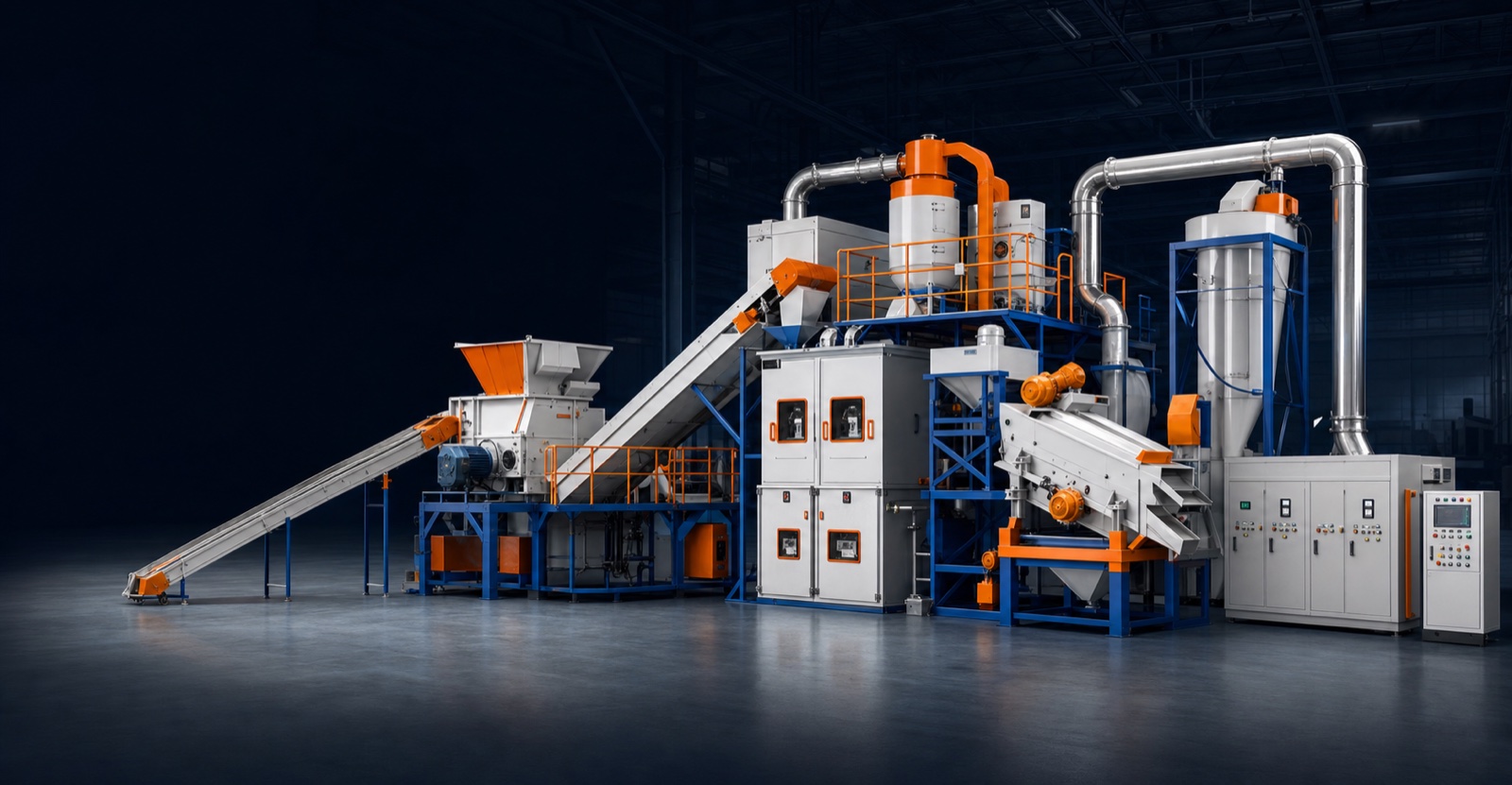
Complete shredding line placeholder
  • Feeding and buffer equipment
  • Primary dual shaft shredder
  • Discharge and transfer conveyors
  • Magnetic or manual separation
  • Secondary shredder and screen
  • Dust, noise and fire-control interfaces

SAFETY

Safety Must Be Designed Into the System

  • Machine guarding and emergency stops
  • Hopper access and conveyor pull cords
  • Electrical isolation and interlocks
  • Safe observation and maintenance access
  • Ejection, dust, fire and explosion review
  • Site-specific risk assessment

The customer remains responsible for local safety, electrical and environmental requirements.

MAINTENANCE

Access Affects Real Operating Cost

  • Cutter, spacer and clearance inspection
  • Bearing, seal and gearbox maintenance
  • Hydraulic filtration where applicable
  • Safe wrapped-material cleaning
  • Fastener and structural checks
  • Clear wear limits and procedures

SPARE-PARTS PLANNING

Plan Wear Parts Before Shipping

  • Cutters, spacers and cleaning fingers
  • Shaft and hydraulic seals
  • Bearings, filters and sensors
  • Contactors and emergency-stop parts
  • Conveyor and gearbox wear parts

PROJECT PROCESS

From Material Review to Operating Shredder

  • 01 Application information
  • 02 Engineering review
  • 03 Material test where needed
  • 04 Technical proposal
  • 05 Drawing confirmation
  • 06 Manufacturing and inspection
  • 07 Factory acceptance
  • 08 Delivery and support

APPLICATION-FIRST ENGINEERING

Why Buyers Work With Mecuvo

The objective is not to sell the largest machine, but to configure a system that can process the material and support the required result.

Application-First

Start with feed, capacity, output and plant conditions.

Material Testing

Verify grip, output and line suitability.

Clear Technical Scope

Define machine, feeding, discharge and options.

Export Coordination

Review dimensions, packing, voltage and documents.

Spare-Parts Planning

Identify wear parts before shipment.

Machines or Complete Lines

Supply standalone or integrated systems.

MACHINE TYPE GUIDANCE

Is a Dual Shaft Shredder the Right Machine?

Choose coarse high-grip reduction for bulky feed; choose screen-controlled systems when a defined final size is the priority.

Dual Shaft

  • Strong coarse primary reduction
  • Bulky and irregular feed
  • Strong self-feeding action
  • Limited uniform-size control
  • Product destruction and volume reduction

Single Shaft

  • Often uses hydraulic pusher
  • Screen-controlled output
  • Better for defined particle size
  • Application-dependent contamination tolerance
  • Secondary or direct sizing duties

Four Shaft

  • Strong self-feeding
  • Screen-controlled output
  • Smaller feed limitation
  • More complex than needed for coarse reduction
  • Precise secondary applications

FREQUENTLY ASKED QUESTIONS

Dual Shaft Shredder FAQ

Answers remain material-dependent until the exact application and machine configuration are confirmed.

They are common names for a shredder using two counter-rotating cutter shafts.
Selection starts with material, dimensions, wall thickness, density, contamination, capacity, feeding and downstream objective.
Capacity is material-dependent. Hollow drums, tires, sheet metal and mixed waste behave differently, so testing is the reliable basis.
Potentially, but cutter geometry and operating settings differ. The expected mix must be disclosed before selection.
A conventional dual shaft shredder produces coarse output with variation. Controlled final size usually requires screening or secondary shredding.
Many primary dual-shaft shredders work without a screen. Screen-controlled or downstream sizing can be configured when required.
The controls can stop and reverse the shafts. Persistent obstructions require isolated operator inspection under an approved safety procedure.
Life depends on material, contamination, hours, cutter material, heat treatment, clearance and maintenance. No universal lifetime is claimed.
Cutter diameter, thickness, hooks and geometry are selected together with shaft, chamber, gearbox and drive.
Yes. Feeding, discharge, magnetic separation, screening and secondary shredding can form a complete line.
The correct choice depends on load variation, shock, reversing, speed control, maintenance capability and infrastructure.
The electrical system is configured according to destination voltage, frequency and confirmed project requirements.
Testing depends on material and sample availability. Send photos, videos and material details so the method can be reviewed.
Provide material composition, photos, dimensions, wall thickness, piece weight, capacity, hours, target output, feeding, downstream process, voltage and destination.

SEND YOUR MATERIAL. DEFINE YOUR TARGET.

Tell Us What You Need to Shred

Send photos or videos, maximum dimensions, material composition, required capacity and target output. We will recommend a suitable shredder, cutter, drive and supporting equipment.